Difference between revisions of "Chemical Oxidation Design Considerations(In Situ - ISCO)"
m (1 revision imported) |
m (1 revision imported) |
(No difference)
| |
Revision as of 04:05, 4 May 2018
In situ chemical oxidation (ISCO) is a soil and/or groundwater remediation technology that uses oxidants to react with contaminants, resulting in their conversion into less harmful products. Key considerations for designing ISCO remediation projects include contaminant type, geochemical conditions, and the chemical delivery method. There are numerous resources for designing and implementing ISCO projects as well as detailed case studies and performance evaluations. Here, we provide supporting information on conceptual site models, milestones/metrics/endpoints, coupling ISCO with other technologies, regulatory considerations, health and safety, key tools, and case studies.
Related Article(s):
CONTRIBUTOR(S): Dr. Michelle Crimi
Key Resource(s):
- ISCO for groundwater remediation: analysis of field applications and performance[1]
- In situ chemical oxidation for groundwater remediation[2]
Introduction
A systematic approach to ISCO screening, design, and implementation can increase the probability that an ISCO project will achieve remediation goals and objectives in a successful manner. Decisions that must be made throughout an ISCO application are generally consistent with those for other in situ groundwater remediation technologies, with some technology-specific details.
Conceptual Site Model
To be effective, all in situ treatment technologies require a sound conceptual site model (CSM) and a set of reasonably achievable treatment goals. The CSM will typically be based on: (a) Site history considering past, current, and future uses, (b) age, type, and location of release(s), (c) site geology and hydrology, (d) previous remediation activities and remedial progress made at the site, (e) applicable regulatory program under which remediation is being conducted, and (f) current site management plan and exit strategy.
ISCO requires the same general level of understanding necessary to select, design, and implement any in situ treatment technology, with additional focus on subsurface biogeochemistry, including: (a) Oxidation-reduction (redox) potential (can provide insight into oxidant persistence), (b) reactivity of subsurface media with the selected oxidant (can control oxidant depletion over time), (c) pH and alkalinity (can influence oxidation chemistry and free radical scavenging), and (d) presence of redox-sensitive metals from mineralogy/geology, dissolved metals data, or site history (can help assess potential for post-treatment toxicity, e.g., Cr)
Much of the information to support CSM development is immediately available in existing site documents and files (i.e., RCRA, CERCLA, State programs, etc.). The Federal Remediation Technology Roundtable provides guidance, including example techniques and instrumentation, for collecting and analyzing field samples to characterize sites where ISCO could be deployed[3]. Because of the frequency of implementing in situ monitored natural attenuation (MNA) at sites for post-ISCO polishing, it is prudent to collect, before and after, ISCO implementation – MNA parameters (e.g., nitrate, iron, sulfate/sulfide, methane, ethene, ethane, carbon dioxide, chloride, hydrogen, total organic carbon, pH, temperature) along with microbiological data using molecular biology tools (e.g., DNA analysis, lipid analysis).
Oxidant Delivery
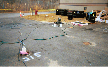
Effective delivery requires delivery of oxidant into the subsurface and transport throughout a target treatment zone (e.g., by advection, [dispersion, diffusion]). Oxidant delivery approaches include[4][5][6][7][8][9][10][11][12][13][14][1][2]: (a) Permanent or temporary injection wells, (b) direct push technology (DPT) for injection, (c) sparging wells or points for ozone injection, (d) infiltration trenches, galleries, or wellpoints installed in the vadose zone (or surface application for vertical migration), (e) recirculation, (f) hydraulic or pneumatic fracturing, (g) mechanical mixing, and (h) horizontal wells.
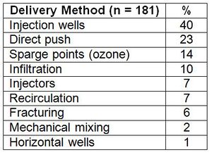
Table 1 shows the frequency of use of different delivery methods used for ISCO at 181 sites[1]. Multiple delivery methods were used at some sites. Delivery of an oxidant is usually conducted using a network of injection wells or probes. The number of oxidant injection points depends on site-specific factors and design features, including presence of man-made structures (e.g., utilities), oxidant type and reaction processes, oxidant delivery concentration and volume, delivery duration and rate, hydraulic conductivity, porosity, heterogeneity, contaminant mass and its distribution, and areal extent of contamination.
Siegrist et al. (2011)[2] provide detailed guidance for selecting the appropriate delivery approach for site-specific hydrogeological conditions and the oxidant selected. ISCO frequently requires the use of two or even three injection events at the same locations or at previously untreated locations. The average number of injections for sites for which case histories were reviewed was about three[1]. Remediation performance assessment using an “Observational Method”, where detailed monitoring results that are collected after an initial injection, are used to guide subsequent injections, is recommended[15]. The Observational Method can be used to help guide/focus any injections following the initial injection to improve cost-effectiveness per injection event. In particular, performance monitoring data can be assessed to focus subsequent injections on untreated zones where unacceptably high contaminant concentrations remain. The use of techniques such as direct push technologies and in situ sensors with data loggers, along with the development of GIS and geostatistical packages used in the field to analyze data, have dramatically improved the ability to apply an Observational Method.
The tendency with ISCO has been to inject just a fraction of a pore volume (PV) of oxidant solution at high concentration into a targeted zone, and to rely on advection, dispersion, or diffusion of oxidant as a means to transport it throughout the remainder of the treatment zone (Fig. 1a). However, research and experience have shown that treatment can be enhanced by increasing the volume of oxidant solution because it can result in an increased radius of influence and the need for fewer injection points per site (Fig. 1b) which can result in lower overall project costs. Increasing the volume by increasing injection rate, where feasible, is more effective than increasing duration. When injected at a higher rate, less oxidant reacts nonproductively within the subsurface. The injection rate and volume is a balancing act based on soil fluid dynamics and treatment goals.
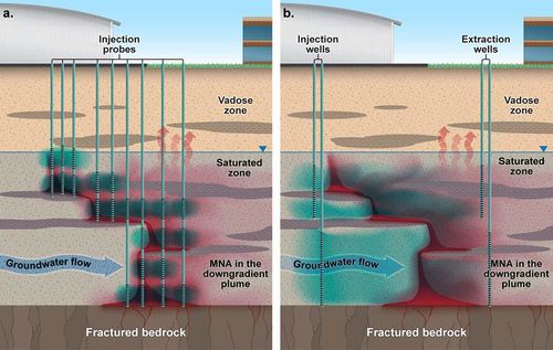
Decision aids and computational tools are available to assist with developing conceptual designs as well as detailed ISCO system designs (e.g., the ESTCP ISCO Spreadsheet Design Tools and Report and User[16]).
Milestones, Metrics, and Endpoints
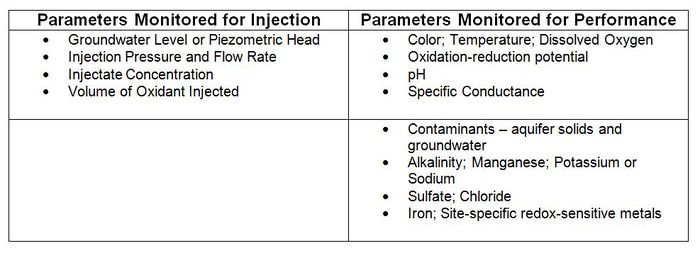
There are parameters commonly included during oxidant delivery monitoring and in monitoring of ISCO effectiveness (Table 2[2]).
Remediation performance assessment (performance monitoring) of ISCO includes operational monitoring for process control (e.g., oxidant concentrations, delivery rates, injection pressure, volume injected) and treatment performance monitoring (for regulatory compliance and site closure). The monitoring program is designed to evaluate/confirm appropriate oxidant injection concentrations and volumes, oxidant distribution/radius of influence, and contaminant destruction. It is also designed to detect and enable management of ISCO effects such as gas generation and changes in temperature, subsurface pressure, and changing water table levels. Monitoring plans should be dynamic and adaptive and use real-time monitoring during oxidant delivery to facilitate optimization.
Coupling ISCO with Other Technologies and Approaches
Treatment of contaminants by other remediation techniques in conjunction with ISCO should be considered at all sites except those where ISCO is clearly capable of achieving clean-up goals as a stand-alone, cost-effective remedy. Pre-ISCO contaminant mass recovery (e.g., by free product recovery) and/or post-ISCO polishing (e.g., bioprocesses) can often increase the likelihood of meeting cleanup goals and potentially reduce treatment times and costs. Many other remedies are suitable for combining with ISCO, though their particular interactions with ISCO should be carefully evaluated. Selection of remedies to combine with ISCO is normally based on:
- Contaminant susceptibility
- Mass distribution
- Site hydrogeology
- Geochemistry
- Reactions between chemical treatment reagents
- Hydrologic impacts of treatment
- Effect of pre-treatment residuals on follow-up ISCO treatment
Regulations and Guidance
ISCO has been used for remediation of contaminated groundwater in every state of the U.S. and several countries worldwide. The permitting process varies from state to state and includes requirements typical for projects using in situ remediation technologies as well as a few requirements specific to ISCO. The Interstate Technology & Regulatory Council (ITRC) provides detailed information regarding typical regulatory barriers, along with examples highlighting the permitting process[17]. Relevant regulations and regulatory issues may include underground injection control, state approvals for materials (e.g., metals content of permanganate solution), RCRA Hazardous Waste treatment, storage, and disposal (TSD), permitting for ex situ mixing and hazardous waste generation, CERCLA “release” or “process” definition, EPCRA reporting, secondary containment, OSHA requirements, potential exacerbation of indoor air exposure, and secondary water quality impacts relative to groundwater standards (e.g., manganese, sulfate, redox-sensitive metals).
Health and Safety
Oxidants are relatively safe chemicals when handled and stored properly. However, accidents have occurred when ISCO was implemented without appropriate caution and attention to health and safety. Primary hazards associated with oxidant use are dermal exposure effects, gas and heat generation, and the potential for uncontrolled reaction through improper storage. It is important to consider the hazards of dusts of solid phase oxidants (e.g., KMnO4 and Na2S2O8), as well as electrical hazards associated with oxidant generation on site (e.g., ozone). Oxidant reactions can be vigorous and exothermic and can result in significant generation of gas and heat, which must be considered in developing site safety and health plans. Chemical manufacturers and vendors should be consulted for oxidant-specific health and safety precautions and protection measures. Engineering controls and appropriate personal protective equipment (PPE) must be employed in handling and mixing oxidants. Site health and safety plans must include safety precautions and appropriate training for the specific oxidant(s) to be used on site, including oxidant activators such as acids or bases.
Tools
Tools are available to aid with screening, selecting, and implementing ISCO for remediation of contaminated groundwater, including:
- ISCO e-protocol for Site-Specific Engineering & Technology Application (ESTCP Project ER-0623[18], based on Siegrist et al., 2011[2])
- Database for ISCO (DISCO)[19]
- ISCO Spreadsheet Design Tool (CDISCO[18], based on Borden et al., 2010[20])
- ITRC ISCO Second Edition Guidance[17]
ISCO Field Demonstrations and Performance
Some examples and summaries of field demonstrations and outcomes of ISCO implementation are:
- Database for ISCO (DISCO)[19]
- U.S. EPA Contaminated Site Clean-Up Information (Clu-In)[21]
- ESTCP Demonstrations: Cost and Performance Reports
- ER-200912 - Cooperative Technology Demonstration: Polymer-Enhanced Subsurface Delivery and Distribution of Permanganate[22]
- ER-200116 – Remediation of DNAPL through Sequential In Situ Chemical Oxidation and Bioaugmentation[23]
- ER-200635 – Using Electrical Resistivity Imaging to Evaluate Permanganate Performance During an In Situ Treatment of a RDX-Contaminated Aquifer[24]
- Detailed case study by Thomson, Hood, and Farquhar (2007)[25]
- Regulatory / Guidance Documents[17]
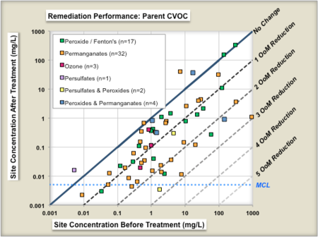
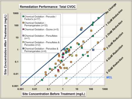
ESTCP Project ER-201120[26] evaluated the performance of 70 chemical oxidation projects at chlorinated solvent sites in terms of the reduction in source concentrations before and after treatment. Figure 3 shows the change in geometric means of parent compound (left panel) and change in geometric means of total chlorinated volatile organic compound (CVOC) concentrations (right panel). Each symbol is a individual in situ remediation project at a specific site. The geometric mean of the before-treatment zone concentration is shown on the X-axis, and the after-treatment zone concentration is shown on the Y-Axis. The different colored symbols represent a different technology subtype for two technologies, in-situ bioremediation and chemical oxidation. The median project was able to reduce the parent compound concentrations in the treatment zone by about 77% (0.6 Orders of Magnitude or OoMs)[26].
Summary
There are numerous resources for designing and implementing chemical oxidation projects. As a commonly used remediation technology, there are wide range of detailed case studies and performance evaluation approaches available as well.
References
- ^ 1.0 1.1 1.2 1.3 1.4 Krembs, F.J., Siegrist, R.L., Crimi, M.L., Furrer, R.F. and Petri, B.G., 2010. ISCO for groundwater remediation: analysis of field applications and performance. Groundwater Monitoring & Remediation, 30(4), 42-53. doi: 10.1111/j.1745-6592.2010.01312.x
- ^ 2.0 2.1 2.2 2.3 2.4 2.5 2.6 Siegrist, R.L., Crimi, M. and Simpkin, T.J. eds., 2011. In situ chemical oxidation for groundwater remediation (Vol. 3). Springer Science & Business Media. 678 pgs. ISBN: 978-1-4419-7825-7. doi: 10.1007/978-1-4419-7826-4 Cite error: Invalid
<ref>tag; name "Siegrist2011" defined multiple times with different content - ^ FRTR (Federal Remediation Technologies Roundtable), 2008. Field Sampling and Analysis Technologies Matrix, Version 1. http://www.frtr.gov/site
- ^ Cline, S.R., West, O.R., Korte, N.E., Gardner, F.G., Siegrist, R.L. and Baker, J.L., 1997. KMnO4 chemical oxidation and deep soil mixing for soil treatment. Geotech. News, 15(5), 25-28.
- ^ Murdoch, L., Slack, B., Siegrist, B., Vesper, S., Meiggs, T., 1997. Hydraulic fracturing advances. Civil Eng. 67, 10A–12A. http://cedb.asce.org/CEDBsearch/record.jsp?dockey=0105818
- ^ Siegrist, R.L., Lowe, K.S., Smuin, D.R., West, O.R., Gunderson, J.S., Korte, N.E., Pickering, D.A. and Houk, T.C., 1998. Permeation dispersal of reactive fluids for in situ remediation: field studies. ORNL/TM-13596. Prepared by Oak Ridge National Laboratory for the US Department of Energy Office of Science and Technology, Washington, DC, USA.
- ^ West, O.R., Cline, S.R., Holden, W.L., Gardner, F.G., Schlosser, B.M., Thate, J.E., Pickering, D.A. and Houk, T.C., 1997. A full-scale demonstration of in situ chemical oxidation through recirculation at the X-701B site (No. ORNL/TM--13556). Oak Ridge National Lab., TN. Report pdf
- ^ Siegrist, R.L., Lowe, K.S., Murdoch, L.C., Case, T.L. and Pickering, D.A., 1999. In situ oxidation by fracture emplaced reactive solids. Journal of Environmental Engineering, 125(5), 429-440. doi:10.1061/(ASCE)0733-9372(1999)125:5(429)
- ^ Siegrist, R. L. Urynowicz, M.A., West, O.R., Crimi, M.L. and Lowe, K.S., 2001. Principles and practices of in situ chemical oxidation using permanganate. Columbus, OH: Battelle Press. ISBN-10: 1574771027. doi: 10.1016/S0304-3894(01)00355-7
- ^ Lowe, K.S., Gardner, F.G. and Siegrist, R.L., 2002. Field pilot test of in situ chemical oxidation through recirculation using vertical wells. Ground Water Monitoring and Remediation, 22, 106-115. doi: 10.1111/j.1745-6592.2002.tb00659.x
- ^ Palaia, T.A. and Sprinkle, C.L., 2004, May. Results from two pilot tests using pneumatic fracturing and chemical oxidant injection technologies. In Proceedings of the International Conference on Remediation of Chlorinated and Recalcitrant Compounds, 4th, Monterey, CA, United States. Paper 5B-04.
- ^ Huling, S. G., and Pivetz, B. E., 2006. In-situ chemical oxidation (No. EPA/600/R-06/072). Environmental Protection Agency, Washington, DC. Office of Water. Report pdf
- ^ Strong, M., Bozzini, C., Hood, D., Lowder, B., 2006. Air and Ozone Sparging of TCE Using a Directionally Drilled Horizontal Well. In Proceedings of the International Conference on Remediation of Chlorinated and Recalcitrant Compounds, 5th, Monterey, CA, United States. Paper M–26. Report pdf
- ^ Haselow, J., Rossabi, R., Escochea, E., Vanek, J., 2008. Delivery of ISCO Reagents Using Soil Blending. Proceedings of Sixth International Conference on Remediation of Chlorinated and Recalcitrant Compounds, Monterey, CA, USA, May 19–22, Abstract L-006.
- ^ Brown, S.M., Lincoln, D.R. and Wallace, W.A., 1989. Application of the observational method to remediation of hazardous waste sites. CH2M HILL.
- ^ Borden, R., Cha, K.Y., Simpkin, T. and Lieberman, M.T., 2010. Development of a Design Tool for Planning Aqueous Amendment Injection Systems Permanganate Design Tool. ESTCP Project ER-200626. ER-200626
- ^ 17.0 17.1 17.2 ITRC, 2005. Technical and Regulatory Guidance for In Situ Chemical Oxidation of Contaminated Soil and Groundwater. Council TITaR, editor. Report pdf
- ^ 18.0 18.1 Siegrist, R.L., 2010. In situ chemical oxidation for groundwater remediation - technology practices manual. ESTCP Project ER-0623. ER-200623
- ^ 19.0 19.1 ESTCP, 2009. Database for ISCO (DISCO). ER-0623 ER-0623
- ^ Borden, R., Cha, K.Y., Simpkin, T. and Lieberman, M.T, 2010. Development of Design Tools for Planning Aqueous Amendment Injection Systems. Permanganate Design Tool. ESTCP Project ER-200626. ER-200626
- ^ USEPA, 2016. In Situ Oxidation Application. U.S. EPA In Situ Oxidation Application site
- ^ ESTCP, 2013. Cost and Performance Report. ER-200912. Report pdf
- ^ ESTCP, 2010. Remediation of DNAPL through Sequential In Situ Chemical Oxidation and Bioaugmentation Cost and Performance. ER200116. Report pdf
- ^ ESTCP 2009. Using electrical resistivity imaging to evaluate permanganate performance during an in situ treatment of an RDX-contaminated aquifer. ER-200635. Report pdf
- ^ Thomson, N.R., Hood, E.D. and Farquhar, G.J., 2007. Permanganate treatment of an emplaced DNAPL source. Groundwater Monitoring & Remediation, 27(4), 74-85. Report pdf
- ^ 26.0 26.1 McGuire, T., 2016. Development of an Expanded, High-Reliability Cost and Performance Database for In-Situ Remediation Technologies. ESTCP Project ER-201120. ER-201120
