Difference between revisions of "Main Page"
| (70 intermediate revisions by 2 users not shown) | |||
| Line 3: | Line 3: | ||
|- | |- | ||
| style="width:55%;" |<center><span style="font-size:175%; line-height: 0.2em; vertical-align:top;"><big><span style="color:#008566">Welcome to '''ENVIRO'''</span> <span style="color:#762a87">'''Wiki'''</span></big></span><br /><br /><br /><span style="font-size:150%; color:#008566; line-height: 0.2em; vertical-align:top;"> Peer Reviewed. Accessible. Written By Experts</span></center> | | style="width:55%;" |<center><span style="font-size:175%; line-height: 0.2em; vertical-align:top;"><big><span style="color:#008566">Welcome to '''ENVIRO'''</span> <span style="color:#762a87">'''Wiki'''</span></big></span><br /><br /><br /><span style="font-size:150%; color:#008566; line-height: 0.2em; vertical-align:top;"> Peer Reviewed. Accessible. Written By Experts</span></center> | ||
| − | + | ||
| − | |||
|- | |- | ||
|<span style="width:55%; line-height: 0.3em;"> The goal of ENVIRO Wiki is to make scientific and engineering research results more accessible to environmental professionals, facilitating the permitting, design and implementation of environmental projects. Articles are written and edited by invited experts (see [[Contributors]]) to summarize current knowledge for the target audience on an array of topics, with cross-linked references to reports and technical literature. </span> | |<span style="width:55%; line-height: 0.3em;"> The goal of ENVIRO Wiki is to make scientific and engineering research results more accessible to environmental professionals, facilitating the permitting, design and implementation of environmental projects. Articles are written and edited by invited experts (see [[Contributors]]) to summarize current knowledge for the target audience on an array of topics, with cross-linked references to reports and technical literature. </span> | ||
| Line 18: | Line 17: | ||
<!-- TODAY'S FEATURED ARTICLE --> | <!-- TODAY'S FEATURED ARTICLE --> | ||
| id="mp-left" class="MainPageBG" style="width:55%; padding:0; vertical-align:top; color:#000;" | | | id="mp-left" class="MainPageBG" style="width:55%; padding:0; vertical-align:top; color:#000;" | | ||
| − | <h2 id="mp-tfa-h2" style="margin:0.5em; background:#cef2e0; font-family:inherit; font-size:120%; font-weight:bold; border:1px solid #a3bfb1; color:#000; padding:0.2em 0.4em;"> Featured article: | + | <h2 id="mp-tfa-h2" style="margin:0.5em; background:#cef2e0; font-family:inherit; font-size:120%; font-weight:bold; border:1px solid #a3bfb1; color:#000; padding:0.2em 0.4em;"> Featured article: PFAS Destruction by Ultraviolet/Sulfite Treatment</h2> |
| − | <div id="mp-tfa" style="padding:0.0em 1.0em;">[[File: | + | <div id="mp-tfa" style="padding:0.0em 1.0em;">[[File:XiongFig1.png|400px|left|link=PFAS Destruction by Ultraviolet/Sulfite Treatment]]<dailyfeaturedpage></dailyfeaturedpage> |
| − | [[ | + | |
| + | [[PFAS Destruction by Ultraviolet/Sulfite Treatment|(Full article...)]] </div> | ||
| style="border:1px solid transparent;" | | | style="border:1px solid transparent;" | | ||
| Line 31: | Line 31: | ||
<slideshow sequence="random" transition="fade" refresh="7500"> | <slideshow sequence="random" transition="fade" refresh="7500"> | ||
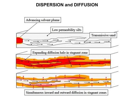
| − | [[File:WH Picture1.JPG|thumb|center|x350px|link= | + | [[File:WH Picture1.JPG|thumb|center|x350px|link=Matrix Diffusion|Molecular diffusion slowly transports solutes into clay-rich, lower permeability zones]] |
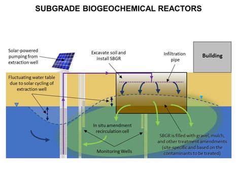
[[File:WH Picture2.JPG|thumb|center|x350px|link=Subgrade Biogeochemical Reactor (SBGR)|Typical subgrade biogeochemical reactor (SBGR) layout. The SBGR is an in situ remediation technology for treatment of contaminated source areas and groundwater plume hot spots<br/>]] | [[File:WH Picture2.JPG|thumb|center|x350px|link=Subgrade Biogeochemical Reactor (SBGR)|Typical subgrade biogeochemical reactor (SBGR) layout. The SBGR is an in situ remediation technology for treatment of contaminated source areas and groundwater plume hot spots<br/>]] | ||
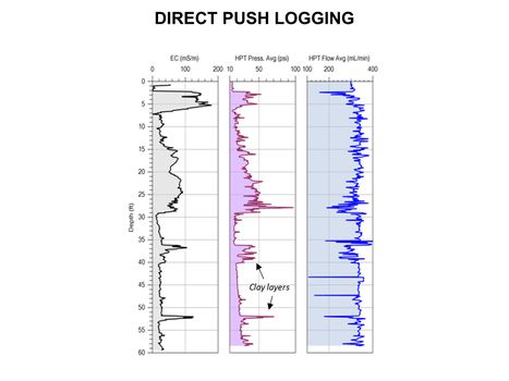
[[File:WH Picture3.JPG|thumb|center|x350px|link=Direct Push Logging|An Hydraulic Profiling Tool (HPT) log with electrical conductivity (EC) on left, injection pressure in middle, and flow rate on the right]] | [[File:WH Picture3.JPG|thumb|center|x350px|link=Direct Push Logging|An Hydraulic Profiling Tool (HPT) log with electrical conductivity (EC) on left, injection pressure in middle, and flow rate on the right]] | ||
| Line 52: | Line 52: | ||
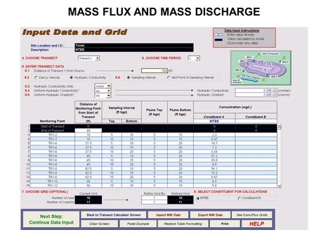
[[File:WH Picture20.JPG|thumb|center|x350px|link=Mass_Flux_and_Mass_Discharge|Data input screen for ESTCP Mass Flux Toolkit]] | [[File:WH Picture20.JPG|thumb|center|x350px|link=Mass_Flux_and_Mass_Discharge|Data input screen for ESTCP Mass Flux Toolkit]] | ||
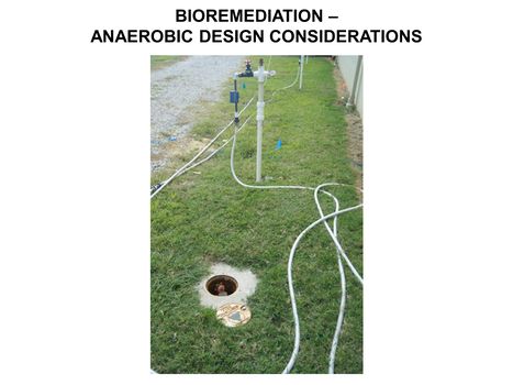
[[File:WH Picture21.JPG|thumb|center|x350px|link=Bioremediation_-_Anaerobic_Design_Considerations|Amendment addition for biobarrier]] | [[File:WH Picture21.JPG|thumb|center|x350px|link=Bioremediation_-_Anaerobic_Design_Considerations|Amendment addition for biobarrier]] | ||
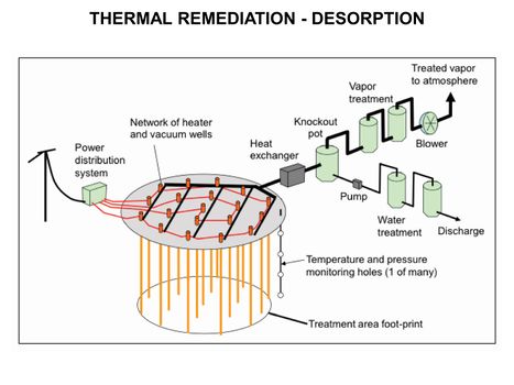
| − | [[File:WH Picture22.JPG|thumb|center|x350px|link= | + | [[File:WH Picture22.JPG|thumb|center|x350px|link=Thermal Conduction Heating (TCH)|Thermal Remediation - Desorption schematic]] |
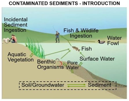
[[File:WH_Picture23.jpg|thumb|center|x350px|link=Contaminated_Sediments_-_Introduction |Key exposure pathways for human health risk from contaminated sediments]] | [[File:WH_Picture23.jpg|thumb|center|x350px|link=Contaminated_Sediments_-_Introduction |Key exposure pathways for human health risk from contaminated sediments]] | ||
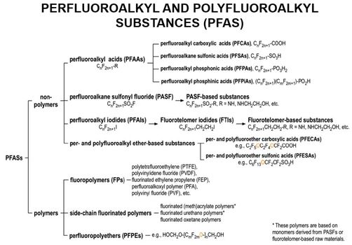
[[File:WH_Picture24.jpg|thumb|center|x350px|link=Perfluoroalkyl_and_Polyfluoroalkyl_Substances_(PFAS)| The PFAS family of compounds]] | [[File:WH_Picture24.jpg|thumb|center|x350px|link=Perfluoroalkyl_and_Polyfluoroalkyl_Substances_(PFAS)| The PFAS family of compounds]] | ||
| Line 79: | Line 79: | ||
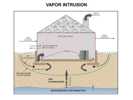
*[[Vapor Intrusion (VI)]] | *[[Vapor Intrusion (VI)]] | ||
**[[Vapor Intrusion - Separation Distances from Petroleum Sources]] | **[[Vapor Intrusion - Separation Distances from Petroleum Sources]] | ||
| − | **[[Vapor Intrusion – Sewers and Utility Tunnels as Preferential Pathways]] | + | **[[Vapor Intrusion – Sewers and Utility Tunnels as Preferential Pathways|Vapor Intrusion - Sewers and Utility Tunnels as Preferential Pathways]] |
| + | **[[Assessing Vapor Intrusion (VI) Impacts in Neighborhoods with Groundwater Contaminated by Chlorinated Volatile Organic Chemicals (CVOCs)|Vapor Intrusion - Assessing VI Impacts in Neighborhoods with Groundwater Contaminated CVOCs]] | ||
<u>'''[[Characterization, Assessment & Monitoring]]'''</u> | <u>'''[[Characterization, Assessment & Monitoring]]'''</u> | ||
| Line 86: | Line 87: | ||
*[[Compound Specific Isotope Analysis (CSIA)|Compound Specific Isotope Analysis (CSIA)]] | *[[Compound Specific Isotope Analysis (CSIA)|Compound Specific Isotope Analysis (CSIA)]] | ||
*[[Direct Push (DP) Technology]] | *[[Direct Push (DP) Technology]] | ||
| − | **[[Direct Push Logging | | + | **[[Direct Push Logging |Direct Push Logging]] |
| − | **[[Direct Push Sampling | | + | **[[Direct Push Sampling |Direct Push Sampling]] |
*[[Geophysical Methods | Geophysical Methods]] | *[[Geophysical Methods | Geophysical Methods]] | ||
| − | **[[Geophysical Methods - Case Studies | Case Studies]] | + | **[[Geophysical Methods - Case Studies |Case Studies]] |
| + | **[[Hydrogeophysical Methods for Characterization and Monitoring of Groundwater-Surface Water Exchanges]] | ||
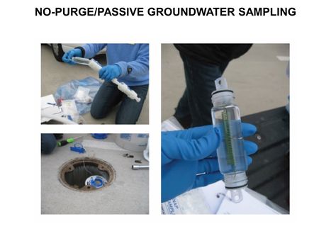
*[[Groundwater Sampling - No-Purge/Passive]] | *[[Groundwater Sampling - No-Purge/Passive]] | ||
*[[Long-Term Monitoring (LTM)|Long-Term Monitoring (LTM)]] | *[[Long-Term Monitoring (LTM)|Long-Term Monitoring (LTM)]] | ||
| − | **[[Long-Term Monitoring (LTM) - Data Analysis | LTM Data Analysis]] | + | **[[Long-Term Monitoring (LTM) - Data Analysis |LTM Data Analysis]] |
| − | **[[Long-Term Monitoring (LTM) - Data Variability | LTM Data Variability]] | + | **[[Long-Term Monitoring (LTM) - Data Variability |LTM Data Variability]] |
| − | *[[Molecular Biological Tools - MBTs | Molecular Biological Tools (MBTs)]] | + | *[[Molecular Biological Tools - MBTs |Molecular Biological Tools (MBTs)]] |
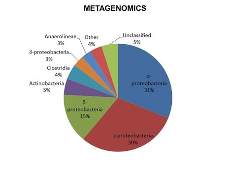
**[[Metagenomics]] | **[[Metagenomics]] | ||
**[[Proteomics and Proteogenomics]] | **[[Proteomics and Proteogenomics]] | ||
**[[Quantitative Polymerase Chain Reaction (qPCR)]] | **[[Quantitative Polymerase Chain Reaction (qPCR)]] | ||
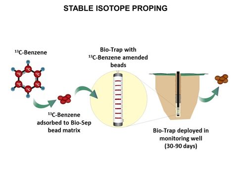
**[[Stable Isotope Probing (SIP)]] | **[[Stable Isotope Probing (SIP)]] | ||
| − | *[[Natural Attenuation in Source Zone and Groundwater Plume - Bemidji Crude Oil Spill | Natural Attenuation in Source Zone and Groundwater Plume -<br /> Bemidji Crude Oil Spill | + | *[[Natural Attenuation in Source Zone and Groundwater Plume - Bemidji Crude Oil Spill |Natural Attenuation in Source Zone and Groundwater Plume -<br />Bemidji Crude Oil Spill]] |
| − | + | *[[OPTically-based In-situ Characterization System (OPTICS)]] | |
| − | |||
| − | |||
| − | |||
| − | |||
| − | *[[ | ||
<u>'''[[Coastal and Estuarine Ecology]]'''</u> | <u>'''[[Coastal and Estuarine Ecology]]'''</u> | ||
| Line 111: | Line 108: | ||
*[[Phytoplankton (Algae) Blooms]] | *[[Phytoplankton (Algae) Blooms]] | ||
| − | |||
<u>'''[[Contaminated Sediments - Introduction | Contaminated Sediments]]'''</u> | <u>'''[[Contaminated Sediments - Introduction | Contaminated Sediments]]'''</u> | ||
*[[Contaminated Sediment Risk Assessment]] | *[[Contaminated Sediment Risk Assessment]] | ||
| + | *[[In Situ Toxicity Identification Evaluation (iTIE) | In Situ Toxicity Identification Evaluation]] | ||
*[[In Situ Treatment of Contaminated Sediments with Activated Carbon]] | *[[In Situ Treatment of Contaminated Sediments with Activated Carbon]] | ||
*[[Mercury in Sediments]] | *[[Mercury in Sediments]] | ||
*[[Passive Sampling of Sediments]] | *[[Passive Sampling of Sediments]] | ||
| + | **[[Sediment Porewater Dialysis Passive Samplers for Inorganics (Peepers)]] | ||
*[[Sediment Capping]] | *[[Sediment Capping]] | ||
| + | |||
| + | | style="width:33%; vertical-align:top; " | | ||
<u>'''[[Light Non-Aqueous Phase Liquids (LNAPLs)]]'''</u> | <u>'''[[Light Non-Aqueous Phase Liquids (LNAPLs)]]'''</u> | ||
| Line 128: | Line 128: | ||
<u>'''[[Munitions Constituents]]'''</u> | <u>'''[[Munitions Constituents]]'''</u> | ||
| − | *[[Munitions Constituents - Alkaline Degradation| Alkaline Degradation]] | + | *[[Munitions Constituents - Abiotic Reduction|Abiotic Reduction]] |
| − | *[[Munitions Constituents - Composting| Composting]] | + | *[[Munitions Constituents - Alkaline Degradation|Alkaline Degradation]] |
| − | *[[Munitions Constituents - Deposition | Deposition]] | + | **[[Pyrogenic Carbonaceous Matter Enhanced Alkaline Hydrolysis]] |
| − | *[[Munitions Constituents - Dissolution | Dissolution]] | + | *[[Munitions Constituents - Composting|Composting]] |
| − | *[[ | + | *[[Munitions Constituents - Deposition |Deposition]] |
| + | *[[Munitions Constituents - Dissolution |Dissolution]] | ||
| + | *[[Munitions Constituents - Electrochemical Treatment|Electrochemical Treatment]] | ||
*[[Metal(loid)s - Small Arms Ranges]] | *[[Metal(loid)s - Small Arms Ranges]] | ||
| − | *[[Munitions Constituents – Photolysis | Photolysis]] | + | *[[Passive Sampling of Munitions Constituents|Passive Sampling]] |
| − | *[[Munitions Constituents - Soil Sampling | Soil Sampling]] | + | *[[Munitions Constituents – Photolysis |Photolysis]] |
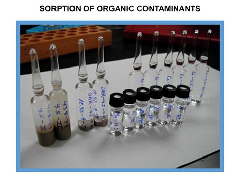
| − | *[[Munitions Constituents - Sorption | Sorption]] | + | *[[Remediation of Stormwater Runoff Contaminated by Munition Constituents |Remediation of Stormwater Runoff ]] |
| − | *[[Munitions Constituents - IM Toxicology | Toxicology]] | + | *[[Munitions Constituents – Sample Extraction and Analytical Techniques|Sample Extraction and Analytical Techniques]] |
| + | *[[Munitions Constituents - Soil Sampling |Soil Sampling]] | ||
| + | *[[Munitions Constituents - Sorption |Sorption]] | ||
| + | *[[Munitions Constituents - IM Toxicology |Toxicology]] | ||
*[[Munitions Constituents- TREECS™ Fate and Risk Modeling|TREECS™]] | *[[Munitions Constituents- TREECS™ Fate and Risk Modeling|TREECS™]] | ||
| Line 143: | Line 148: | ||
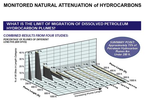
*[[Monitored Natural Attenuation (MNA) of Chlorinated Solvents| MNA of Chlorinated Solvents]] | *[[Monitored Natural Attenuation (MNA) of Chlorinated Solvents| MNA of Chlorinated Solvents]] | ||
| + | **[[Estimating PCE/TCE Abiotic First-Order Reductive Dechlorination Rate Constants in Clayey Soils Under Anoxic Conditions]] | ||
| + | *[[Monitored Natural Attenuation (MNA) of Fuels| MNA of Fuels]] | ||
*[[Monitored Natural Attenuation (MNA) of Metal and Metalloids| MNA of Metals and Metalloids]] | *[[Monitored Natural Attenuation (MNA) of Metal and Metalloids| MNA of Metals and Metalloids]] | ||
| − | |||
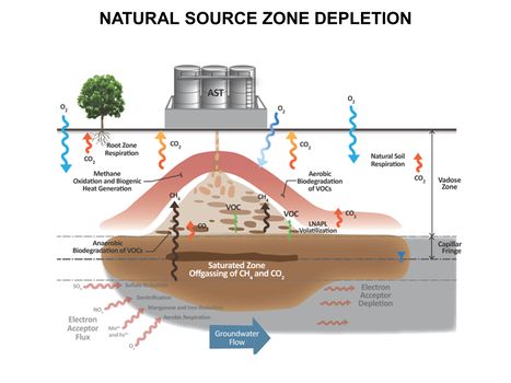
*[[Natural Source Zone Depletion (NSZD)]] | *[[Natural Source Zone Depletion (NSZD)]] | ||
*[[Monitored Natural Attenuation - Transitioning from Active Remedies| Transitioning from Active Remedies]] | *[[Monitored Natural Attenuation - Transitioning from Active Remedies| Transitioning from Active Remedies]] | ||
| Line 150: | Line 156: | ||
<u>'''[[Perfluoroalkyl and Polyfluoroalkyl Substances (PFAS)]]'''</u> | <u>'''[[Perfluoroalkyl and Polyfluoroalkyl Substances (PFAS)]]'''</u> | ||
| + | *[[Hydrothermal Alkaline Treatment (HALT)]] | ||
| + | *[[Lysimeters for Measuring PFAS Concentrations in the Vadose Zone]] | ||
| + | *[[PFAS Destruction by Ultraviolet/Sulfite Treatment]] | ||
*[[PFAS Ex Situ Water Treatment]] | *[[PFAS Ex Situ Water Treatment]] | ||
| + | **[[PFAS Treatment by Anion Exchange]] | ||
| + | *[[PFAS Monitored Retention (PMR) and PFAS Enhanced Retention (PER)]] | ||
*[[PFAS Soil Remediation Technologies]] | *[[PFAS Soil Remediation Technologies]] | ||
*[[PFAS Sources]] | *[[PFAS Sources]] | ||
| + | *[[PFAS Toxicology and Risk Assessment]] | ||
*[[PFAS Transport and Fate]] | *[[PFAS Transport and Fate]] | ||
*[[PFAS Treatment by Electrical Discharge Plasma]] | *[[PFAS Treatment by Electrical Discharge Plasma]] | ||
| + | *[[Photoactivated Reductive Defluorination - PFAS Destruction | Photoactivated Reductive Defluorination]] | ||
| + | *[[Reverse Osmosis and Nanofiltration Membrane Filtration Systems for PFAS Removal]] | ||
| + | *[[Thermal Conduction Heating for Treatment of PFAS-Impacted Soil]] | ||
| + | *[[Transition of Aqueous Film Forming Foam (AFFF) Fire Suppression Infrastructure Impacted by Per and Polyfluoroalkyl Substances (PFAS)| Transition of Aqueous Film Forming Foam Fire Suppression Infrastructure Impacted by Per and Polyfluoroalkyl Substances]] | ||
| + | | style="width:33%; vertical-align:top; " | | ||
<u>'''[[Regulatory Issues and Site Management]]'''</u> | <u>'''[[Regulatory Issues and Site Management]]'''</u> | ||
| Line 165: | Line 182: | ||
*[[Sustainable Remediation]] | *[[Sustainable Remediation]] | ||
| − | + | <u>'''[[Remediation Technologies]]'''</u> | |
*[[Amendment Distribution in Low Conductivity Materials]] | *[[Amendment Distribution in Low Conductivity Materials]] | ||
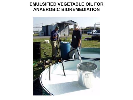
*[[Bioremediation - Anaerobic|Anaerobic Bioremediation]] | *[[Bioremediation - Anaerobic|Anaerobic Bioremediation]] | ||
| Line 198: | Line 215: | ||
<u>'''[[Soil & Groundwater Contaminants]]'''</u> | <u>'''[[Soil & Groundwater Contaminants]]'''</u> | ||
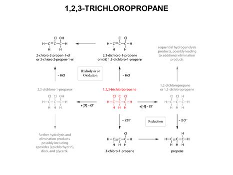
| + | *[[1,2,3-Trichloropropane]] | ||
*[[1,4-Dioxane]] | *[[1,4-Dioxane]] | ||
*[[Chlorinated Solvents]] | *[[Chlorinated Solvents]] | ||
| Line 205: | Line 223: | ||
*[[Petroleum Hydrocarbons (PHCs)]] | *[[Petroleum Hydrocarbons (PHCs)]] | ||
*[[Polycyclic Aromatic Hydrocarbons (PAHs)]] | *[[Polycyclic Aromatic Hydrocarbons (PAHs)]] | ||
| − | |||
|} | |} | ||
|} | |} | ||
|} | |} | ||
Latest revision as of 12:37, 7 May 2026
Peer Reviewed. Accessible. Written By Experts | |
| The goal of ENVIRO Wiki is to make scientific and engineering research results more accessible to environmental professionals, facilitating the permitting, design and implementation of environmental projects. Articles are written and edited by invited experts (see Contributors) to summarize current knowledge for the target audience on an array of topics, with cross-linked references to reports and technical literature. | See Table of Contents |
Featured article: PFAS Destruction by Ultraviolet/Sulfite Treatment |
Enviro Wiki Highlights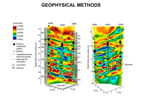 High-resolution 3D cross-borehole electrical imaging of contaminated fractured rock at the former Naval Air Warfare Center in New Jersey. Cross-borehole resistivity tomography imaging is a geophysical technique that can be used for site characterization and monitoring by observing variations in the electrical properties of subsurface materials |